

Autopilot Drone

ABOUT THIS PROJECT
Normally we see drones controlled using an RF remote, or for autopilot using a GPS module to control it automatic by giving proper direction by it. But in my project, I have gone about things in another way using an Arduino Uno.
The main objective of this project is to collect data and 2D video information from a particular known area. In order to get the information, we must to assign the values of length and width that the drone can travel using Arduino programming.
As its name suggests, autopilot means that the drone will be handled by itself, while controlling action of the drone will be handled by a flight controller that has built-in sensors to balance the drone. An Arduino Uno is the brain of the system, which gives the proper signal to flight controller. To maintain stability and sustained operation, I used an OpenPilot CC3D microcontroller (or any flight controller), along with a camera to capture live data with weather monitoring sensors. Finally, the system includes a Bluetooth module to turn the dronon/off and display the live data using a Android mobile device.
ARDUINO UNO
 as we know the arduino Uno is a Atmega Micro controller. here i generated PWM signals to control the Drone.


CC3D flight Controller:
as we seen in above fig shows the a flight controller which having inbuilt gyro and accelerator controller and auto leveling features.
But these micro controllers company provides its own software to program it, and its is user friendly to use.
these micro controller needs a PWM signals for input to control the individual BLDC motors. these signals will be generated by arduino uno.
TYPES OF DRONE DESIGNS
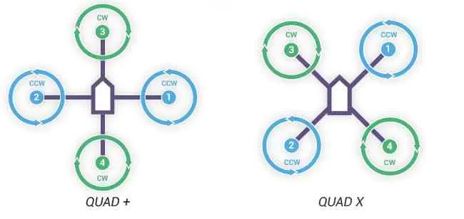
as you see above there are two types of drone designs available for quad format drones, depending upon what direction you place the flight controller you can chose the quad format
the direction indication will be printed with respect chosen flight controllers, with respect to the chosen format the propeller direction also most important, CW (clock wise) and CCW (counter clock wise).
ESC CONNECTIONCLOCK WISE
 Clock wise we need to connect the wires as shown above

for Counter Clock wise we need to interchange any two wires so that phase of an voltage apply to motor will so it changes the motor direction
MOTOR-ESC-FLIGHT CONTROLLER CONNECTION


ESC CONTROL CONNECTION
SC also having a 3 wires with 2 power cables,
these 3 wires having VCC, GROUND and INPUT SIGNAL pin which takes data from FLIGHT CONTROLLER to spin the BLDC Motors.
other 2 Wires are power cables rated for higher current so use thicker wires, and these cables are common with the battery.
FINAL WIRING DIAGRAM WITH ARDUINO UNO

here i used a UART protocal but no data is converted parallel to serial. direct PWM signals are applied from arduino to CC3d with respect to delay.
MOBILE APPthe above snap show the android application which is build using an open source website which mentioned below. using this app we can turn on and turn off the drone. and having another feature which makes we can get the sensor data in the serial window, that is a mobile phone.
buttons
start : this button will boots up the micro controller (CC3D flight controller)
mov : this makes drone to fly and does its operation which is programmed inside the arduino Uno
stop : it is a emergency stop button to turn off the drone (due to auto pilot drone no remote controller is present so provided extra button)

![Download Antim: The Final Truth (2021) Hindi Movie Cam-Rip || 480p [400MB] || 720p [1GB] || 1080p [2GB]](https://lh3.googleusercontent.com/blogger_img_proxy/AEn0k_vGkAaD7fIpJbcMUDvnQeyCUjfVlGlcXbP8-bP3DV7sGROvaOjqjjB5Zb9ePb_HkhXsYp2rZIn0vAFWgT-NX9wLelDywQTWpBpgAHC0VzBUHM9ST_QZjiHzmKZGu1gIJgWYp7nrKmSSTcGa=w72-h72-p-k-no-nu)
![18+Download All Ladies Do It (1992) Full Movie [In Italian With English Subs] WEB-DL 480p [350MB] || 720p 10BIT HEVC [500MB] || 720p [800MB] || 1080p [2GB]](https://blogger.googleusercontent.com/img/a/AVvXsEgp5Z5uySC3woxAW9a2FV1jV3HAoAFfldsvOX7rDp6LmwhkKPAnHW1ax-8x9DfuAD1VO-QxZjMD3f306FKxu4R82x_y4Bp4JUhjJ17wf3E3BeTBS3uPOmSgC5b3mYUgaTA605WrYB7lEqe-9erbQTPcQZPWNwfqSpG7k4J09WsYNDvIu-LYy7VpEb6skw=w72-h72-p-k-no-nu)
![Download Red Notice (2021) Dual Audio {Hindi-English} WeB-DL 480p [500MB] || 720p [1GB] || 1080p [3.7GB]](https://blogger.googleusercontent.com/img/a/AVvXsEitiYVZrfz3LRXaBbIo8hY9-1DAZf-OnTeuwFprvV0QKlP09hCZPgwRDYDwrTLJh1TByJfBu5xv0gGss_DfNDkDhZuhtnKzpnhenPVSQgK84ig4oUKtiOP36EyFWWxdAkO8AhSTV_R8i1dGaXHiy6ReOvzuHBHNBXGbb4yubY-WCfUuk178t30IysDfiA=w72-h72-p-k-no-nu)


![Download Eternals (2021) CAMRip V2 [Hindi & English] 480p [450MB] || 720p [1.1GB]](https://blogger.googleusercontent.com/img/a/AVvXsEjSk3eYxYp0OsH_bENzmEPcCS1rHDOobr74C0XIwQ1lgfO9BZi0hGIxSvEEHtypT3gkBRbSVAfhR9yUhTOJuw-jIYFmh3BBv6iGacXOMmikzCk9jD6Seha46-dpfDUY6bo9ZA60Ivt7uns3xNyoVpTtTejnaic6UzyhtcPuasTGQQV1YlCdBOpk7T1rCg=w72-h72-p-k-no-nu)
![Download 18+ A Man and A Woman (2016) Dual Audio (Hindi-Korean) 480p [400MB] || 720p [950MB] || 1080p [2.1GB]](https://lh3.googleusercontent.com/blogger_img_proxy/AEn0k_v9E8It08vcbyEwzkfLPQ6bvV1OzqYTwA_b49njrXEMczUHMWFMMTCrVHnfBBwelqGol7pn8HZu2ZO23rjXYVX4W4zaGjLOD5ktY7zC2Lsk4eaG7ENoO_2DBw=w72-h72-p-k-no-nu)


0 Comments