Building DIY Drone from Scratch Part 2: Using Arduino Nano as Flight Controller
Overview
If you’re a drone enthusiast and love being creative about drones, then this instructable is for you! We build a really cheap DIY drone from ballpoint pen ink tubes and thermocol in Part 1 of this series. Part 2 guides you to build your own DIY Arduino Drone which will be ready to use on its own OR along with a GPS “follow me” capability which will be discussed in the next part. The easy-to-build mini drone follows you on your way.
It uses Bluetooth to communicate with your smartphone and utilizes the GPS coordinates of your cell phone to track you wherever you go. This autonomous drone lets you do your work and minimizes the headache of manual control. Let’s see what goes into making this cheap follow me mini quadcopter.
Components for the DIY Arduino Drone
Arduino Nano: It’s the brain of your drone. It’ll control its movement and integrate other circuits.
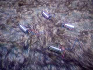
DIY Arduino Nano2. A mini-drone kit that includes: a. 4 miniature motors: You can find them at an electronics hobby shop. Aim for a motor with a rating of 400-500 KV.
DIY Arduino miniature motorsb. 4 motor jackets: Used to hold the motors in place. c. 4 propellers: Preferably, choose a diameter of 10cm. While buying, make sure the propellers fit firmly on the motor’s rotors
DIY Arduino drone-propellersd. Li-polymer battery: A 3.7V battery with a rating of 300-500mAh and 25C would be enough to give a flight time of 10-15 minutes.
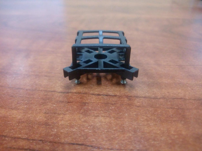
DIY Arduino Nano battery chargere. Battery charger: Choose a 3.7V battery charger, perhaps bought with the battery. f. Frame: You can even build one of your own, or you can get one from amazon.
DIY Arduino frame3. A Bluetooth module: Choose an HC-05/HC-06 Bluetooth module. You can find it online for less than DIY Arduino bluetooth module 4. A NEO-6M-001 GPS module: It’s used to get the current coordinates of the drone. You can find it online for just
DIY Arduino GPS module
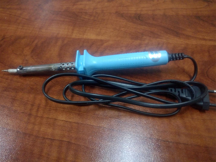
5. Soldering rod and soldering wire: To solder components on the perf board.
soldering rod and wire
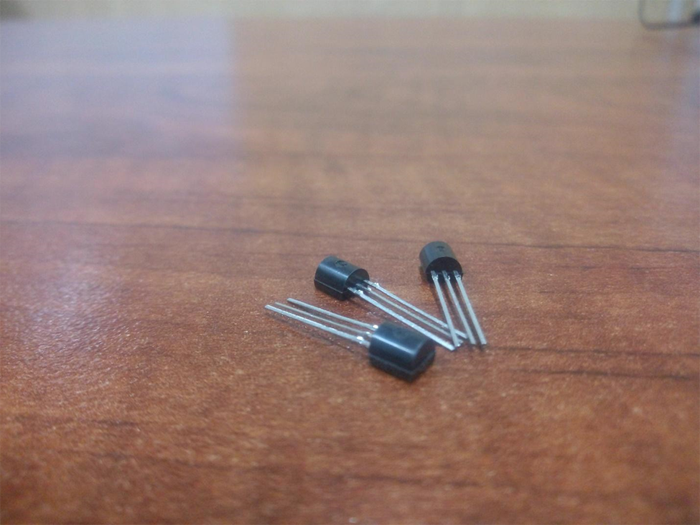
6. Transistors: Three pieces of 2N2222 NPN bipolar transistors
bipolar transistors
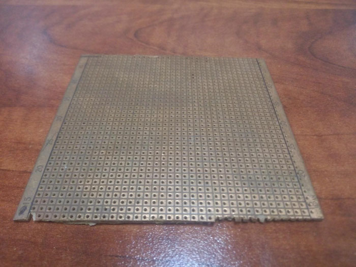
7. Perf board/ PCB: It’s needed to mount the circuit.
Perf Board / PCB
8. Cutter: Needed to cut the perf board. 9. Hot glue/tape: Will keep the circuit in place.
Step 1: Assembling Your Drone
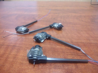
As the first step, you need to build a mini-drone. Get the motors and mount them in the jackets such that the wires are stretched out of the small opening.
Get the motors and mount them in the jackets
Now, insert the wires in the arms as shown in the picture. You can use pen ink tubes to build your own arms.nsert the wires in the arms as shownConnect the central assembly frame to the other end of the arms
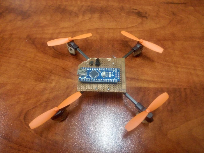
Connect the central assembly frame to the other end of the arms and fasten the screws of the arms.Connect the propellers to the motors.
Step 2: Connecting Motors to Arduino
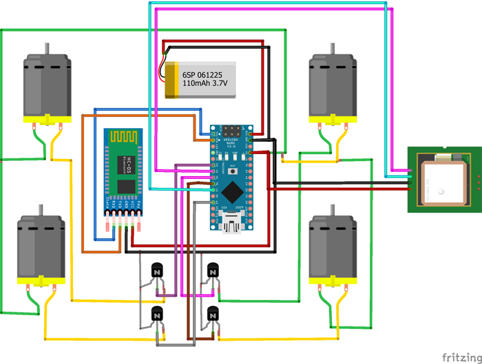
Now, you need to connect your motors to your Arduino Nano. Make connections as shown in the schematic diagram. You need to MIND THE POLARITY of the motors; otherwise, your drone won’t fly. Motors connected to opposite arms should spin in the same direction (see the picture showing the direction of rotation of propellers). Moreover, to provide the rated current to the motors, you need to add transistors, as the Arduino itself isn’t enough to supply the required current to the motors. Insert the legs of the components into the perf board and solder them. Make connections as follows:
Motor RF (Right Front)
Wire 1 (Motor) -> Collector (Pin 1) of Transistor 1
Wire 2 (Motor) -> +5V
Base (Pin 2) of Transistor 1 -> Pin 6 (Arduino)
Motor LF (Left Front)
Wire 1 (Motor) -> Collector (Pin 1) of Transistor 2
Wire 2 (Motor) -> +5V
Base (Pin 2) of Transistor 2 -> Pin 8 (Arduino)
Motor LB (Left Back)
Wire 1 (Motor) -> Collector (Pin 1) of Transistor 3
Wire 2 (Motor) -> +5V
Base (Pin 2) of Transistor 3 -> Pin 9 (Arduino)
Motor RB (Right Back)
Wire 1 (Motor) -> Collector (Pin 1) of Transistor 4
Wire 2 (Motor) -> +5V
Base (Pin 2) of Transistor 4 -> Pin 12 (Arduino)
If a motor doesn’t move in the intended direction, swap its pins.
There you go, now you have a fully functional Arduino powered DIY Mini Drone to fly around the house or outside. But do you want a hands free version that can follow you almost anywhere? For the next part of this Arduino DIY Drone series we will be teaching you how to set up a GPS tracking mechanism which syncs with your phone.
Ut enim ad minima veniam, quis nostrum exercitationem ullam corporis suscipit.
Web Development
Ut enim ad minima veniam, quis nostrum exercitationem ullam corporis suscipit.
Web Design
Ut enim ad minima veniam, quis nostrum exercitationem ullam corporis suscipit.
App Design
Ut enim ad minima veniam, quis nostrum exercitationem ullam corporis suscipit.
We Are Infity, We Are Best.
It is a long established fact that a reader will be distracted by the readable content of a page when looking at its layout. The point of using Lorem Ipsum is that it has a more-or-less normal distribution of letters, as opposed to using 'Content here, content here'.


 There you go, now you have a fully functional Arduino powered DIY Mini Drone to fly around the house or outside. But do you want a hands free version that can follow you almost anywhere? For the next part of this Arduino DIY Drone series we will be teaching you how to set up a GPS tracking mechanism which syncs with your phone.


![Download Antim: The Final Truth (2021) Hindi Movie Cam-Rip || 480p [400MB] || 720p [1GB] || 1080p [2GB]](https://lh3.googleusercontent.com/blogger_img_proxy/AEn0k_vGkAaD7fIpJbcMUDvnQeyCUjfVlGlcXbP8-bP3DV7sGROvaOjqjjB5Zb9ePb_HkhXsYp2rZIn0vAFWgT-NX9wLelDywQTWpBpgAHC0VzBUHM9ST_QZjiHzmKZGu1gIJgWYp7nrKmSSTcGa=w72-h72-p-k-no-nu)
![18+Download All Ladies Do It (1992) Full Movie [In Italian With English Subs] WEB-DL 480p [350MB] || 720p 10BIT HEVC [500MB] || 720p [800MB] || 1080p [2GB]](https://blogger.googleusercontent.com/img/a/AVvXsEgp5Z5uySC3woxAW9a2FV1jV3HAoAFfldsvOX7rDp6LmwhkKPAnHW1ax-8x9DfuAD1VO-QxZjMD3f306FKxu4R82x_y4Bp4JUhjJ17wf3E3BeTBS3uPOmSgC5b3mYUgaTA605WrYB7lEqe-9erbQTPcQZPWNwfqSpG7k4J09WsYNDvIu-LYy7VpEb6skw=w72-h72-p-k-no-nu)
![Download Red Notice (2021) Dual Audio {Hindi-English} WeB-DL 480p [500MB] || 720p [1GB] || 1080p [3.7GB]](https://blogger.googleusercontent.com/img/a/AVvXsEitiYVZrfz3LRXaBbIo8hY9-1DAZf-OnTeuwFprvV0QKlP09hCZPgwRDYDwrTLJh1TByJfBu5xv0gGss_DfNDkDhZuhtnKzpnhenPVSQgK84ig4oUKtiOP36EyFWWxdAkO8AhSTV_R8i1dGaXHiy6ReOvzuHBHNBXGbb4yubY-WCfUuk178t30IysDfiA=w72-h72-p-k-no-nu)


![Download Eternals (2021) CAMRip V2 [Hindi & English] 480p [450MB] || 720p [1.1GB]](https://blogger.googleusercontent.com/img/a/AVvXsEjSk3eYxYp0OsH_bENzmEPcCS1rHDOobr74C0XIwQ1lgfO9BZi0hGIxSvEEHtypT3gkBRbSVAfhR9yUhTOJuw-jIYFmh3BBv6iGacXOMmikzCk9jD6Seha46-dpfDUY6bo9ZA60Ivt7uns3xNyoVpTtTejnaic6UzyhtcPuasTGQQV1YlCdBOpk7T1rCg=w72-h72-p-k-no-nu)
![Download 18+ A Man and A Woman (2016) Dual Audio (Hindi-Korean) 480p [400MB] || 720p [950MB] || 1080p [2.1GB]](https://lh3.googleusercontent.com/blogger_img_proxy/AEn0k_v9E8It08vcbyEwzkfLPQ6bvV1OzqYTwA_b49njrXEMczUHMWFMMTCrVHnfBBwelqGol7pn8HZu2ZO23rjXYVX4W4zaGjLOD5ktY7zC2Lsk4eaG7ENoO_2DBw=w72-h72-p-k-no-nu)


0 Comments